
Just recently, at DevConf, I talked about my journey building a laser engraver. Here, I attempt to help you follow along and build your own.
This comes with a couple of caveats.
- If you want a super accurate device, buy one. Getting the tension right on your own, and with the parts I’ve modelled it is really hard.
- If you want to improve on the code or the design, go ahead. This is all open source, and you can do what you want. If you want to put your changes back into the main system, open a pull request on GitHub, and I’ll look at it at some point.
- This isn’t the best tutorial in the world. I wrote it on a plane, from memory. I also have some aspects which are only available on GitHub. I’m afraid you are going to find this more challenging than IKEA or Decofurn furniture builds.
- Additionally, I assume a base level of DIY figure-it-out ability. Which means my instructions may be incomplete, or contain choices. With great power, comes great complexity.
Getting started
You are going to need some specialised equipment to get yourself going on this project. Or you are going to need to have a chat to one of your friendly local maker types who have such equipment. By which I mean, many of the parts for this project are 3D printed. Don’t worry, I have a list and full set of files that you will need in the stl-files folder of the GitHub project.
I also recommend that you be comfortable with the use of a multi-meter, soldering iron, and crimping pliers. There are a fair number of micro-electronics involved, and if you don’t want a rats nest of wires plugged haphazardly into a breadboard, you’re going to be re-wiring at least once.
So, to start out you need to get these parts printed in your preferred colour and type of plastic. When I made this, I used the cheapest ABS I could find, which gave me a surprisingly nice coffee colour for all my parts. Given my liking for wood, this worked for me. Your local printer might have their own supply, so do whatever works and what you can afford.
So many parts
There are obviously not just the 4D printed parts. You are also going to need to invest in some parts from your favourite electronics or maker shop. I recommend looking at Communica, DIY Eletronics, Micro Robotics and Netram to find the best prices on all of these parts. Once again, the list is available in the GitHub project. The numbers of pulleys and timers are based specifically for this build. You may decide you want some spares, or that you think they would be fun for other projects. Feel free to increase your order to meet your personal needs.
For the wiring, I have given some recommendations, but again, your mileage may vary. I was not particularly scientific when thinking through how much wire I ended up using, and in the case of the crimping kit, I know myself. Having a kit like that on hand is just useful. Going a little over the top is not going to be a problem, in fact you may already have appropriate wire left over from some other project. Mix and match as much as you want.
When it comes to linear shafts and bearing, you once again have some choices to make. I have chosen 8mm shafts and bearings, and so designed the parts to work with those. 10mm would not be unreasonable, and you may feel they will be a bit more stable. I also set the lengths to what I wanted to build. Picked somewhat arbitrarily from what I could find available at the beginning. Feel free to go bigger or smaller, just remember that your length of timing band (total) will be roughly the total length of steel you purchase. Anything less, and you’re going to run into issues.
You also need a device to drive the laser. The code for this device assumes you are using a Raspberry Pi, which is why I have listed some options for one of those in the parts list. You can pick whatever size of Pi you like, as long as you have enough GPIO pins available to run all the controllers. They do not need to be wired in the same configuration as mine, since you can simply set the defult_pins.ini to reference the pins you end u actually using.
The final big parts are the power supply and the laser unit. The laser itself is only restricted by the fact that I designed the mounting plate based on the measurements of this precise unit. Feel free to pick up something more powerful if you want to be able to use this as a cutter as well as an engraver. If, like me, you are happy just drawing pictures, then the slightly lower wattage is going to be plenty. Do not forget the protective green glasses. Your eyesight is sensitive, and the narrow band, high intensity, blue light of this laser could cause irreparable damage. The power supply needs to be able to provide a high enough voltage for each of your components. For the most part 12V will be plenty, in fact you will need to step some pieces down to 5V. If you buy a more powerful laser, or bigger motors, you may want to look at a 24V power supply.
Oh gosh, I nearly forgot the motors. Kind of critical. I have two different sizes used here, and the end blocks reflect that. You should probably buy two of the smaller ones, you don’t need the increased power, I just happened to have one of these things on hand. So I made use of it. You can mount it with a block of whatever arbitrary thing in the gap below, or you can wait and see if I have uploaded the alternative pieces.
Putting it together
OK, so you’ve spent money, and you’ve had the printer going for a couple of days. Let’s talk about putting the pieces together.
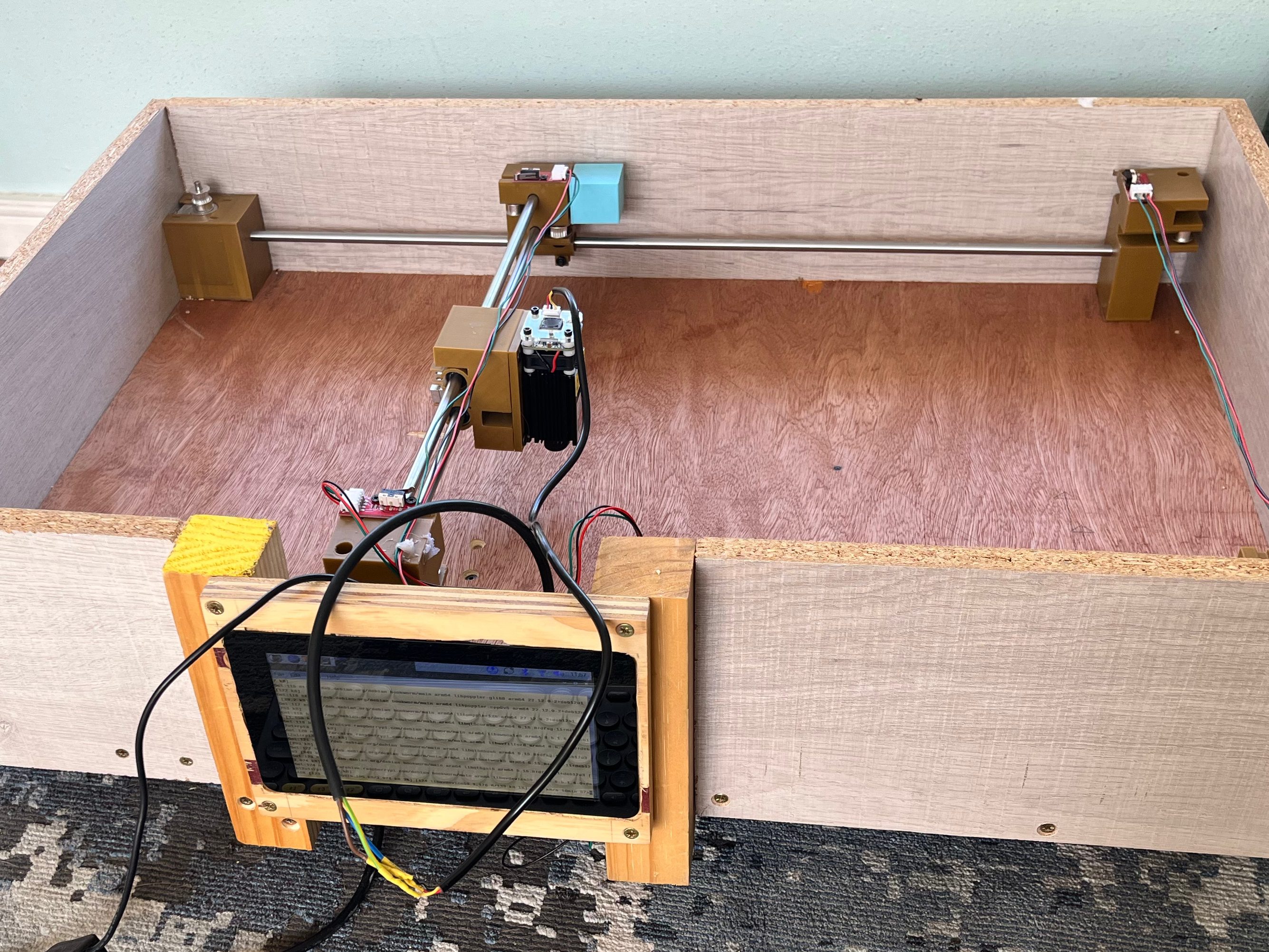
Start by making sure you know which piece is going where. You have four corner pieces, two labelled X and two labelled Y. This refers to the direction of the motor they are in line with. You have two Y-Sliders. The fixed slider goes on the rail between the Y motor and the Y corner. The loose slider goes on the opposite rail. Each of these sliders has pockets for magnets, use the back of a pencil to force them in if you need to. The X rail will be fitted into these holes, and the steel shafts will snap in place with the magnets. You also have an X-slider, set this on the double rails with the laser mount pointed away from the motors (this is why I ended up with a buffer block).
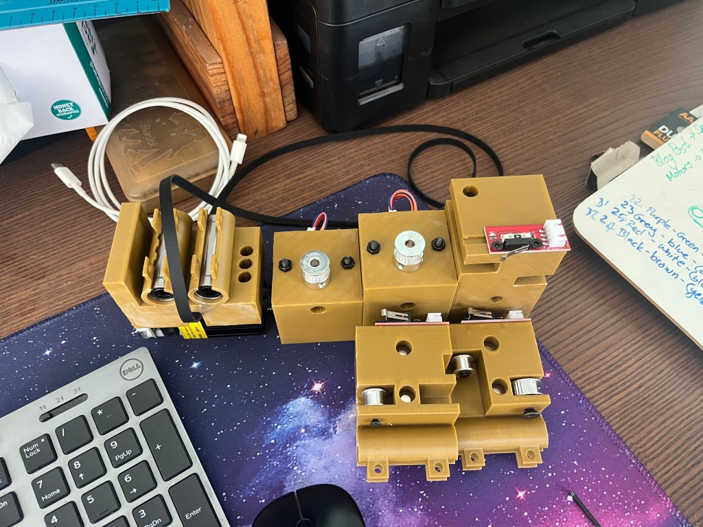


Some of your pulleys have a 5mm bearing, others have a 3mm bearing. You should be able to screw them into the appropriate pockets as long as you use 3mm or 5mm screws of the right length.
The size of your base board will depend on the length of your steel. The measurements in the plan are good for the length of steel I have used. If you adjusted the steel you are going to also need to adjust the size of the base. One you have a base board cut to the right size, mark and drill holes to screw down the corner blocks. Don’t forget to put the Y-sliders and rails together before you screw down the corners, those blocks are not going anywhere once connected to the board. This gives stability to the device with the shaking motion of the stepper motors.
Attaching the timing band may require an extra pair of hands (or you might be very persistent). Thread one band all around the lower set of pulleys, and connect it on the fixed Y-slider. Pull the ends together as tightly as you can, don’t worry about snapping things, the bands are incredibly strong, and the tighter they are the smoother your drawing will be. Thread the second length of band through the upper level of pulleys and connect it on the X-slider. As you pull this one tight you will notice that the whole system becomes more rigid. Again, you want this as tight as possible.
There is a small amount of extra tension you can apply when you attach the motors in their blocks. If you wait until after the bands are in to tighten their screws you can push them as far back as possible to get a little more smoothness. Unfortunately, this is not a brilliant way to tension the system. Which is why I said at the top that if you want really accurate results you should purchase a manufactured device. Those are often built with a different system of rails which offers more stability, and relies less on the timing bands.
Wiring
All the physical pieces in place, your next step is to get all the wiring right. It is up to you how you choose to do it, but if you are powering multiple circuit boards from a single source, do remember that you should connect them in parallel, else your voltage will be lowered as you get through the circuit.
Each board should have a ground pin, a voltage pin, and a control pin. By convention voltage is read, ground is black, and power is colourful. Your motors are an exception, they have four inputs, none of which is voltage. The control board on the other hand requires two different voltage inputs, one at 12V (or more if you’re brave) and one at 5V. It then also has multiple control inputs to allow for micro steps.
When you are setting up the motors, you are going to need to get all the setting right. To achieve this, I followed the instructions from Polulu who originally made the chip. All the details you need are there, or in this awesome Ardufocus article. Particularly the details on tuning the potentiometer using a multimeter.
When you connect each piece to the Pi, make sure you keep track of which device is controlled by which pin so you can set up the code correctly.
Drivers
At this point, you may either have a rats nest of wires so you can start testing, or you may be supremely confident in your (and my) skills and have the whole thing wired beautifully. It is time to start things moving. You may choose how you pull the driver files to your device. I found a git pull to be the most convenient. However you do it, connect to your Pi, pull the driver-files from GitHub, and run a pip install against the requirements file. This will set you up with pigpio and numpy.
One of the complexities of using pigpio is that you need to start the daemon on the device. A simple sudo pigpiod will start it running with the default settings, these are perfect for running the driver code locally. Now, if you run python src/engrave.py you will bring up the laser command line. This allows you to initialise the pins, and give commands to your device. Type ? in the command line to get a full set of available options.
Power on your components after initializing pins to avoid accidentally starting the laser pin “on”, and run some test movement commands. You can also do a test burn using the included Axes.gc file which will draw a set of axes on the base board.
Have fun
I recommend using Inkscape and the Jtech extension to generate your g-code files. But if you have a tool like LightBurn or something else which you are used to using, it should be compatible with Marlin. Make sure you set the laser commands to M03 for on and M05 for off, and you are good to go.
I haven’t given plans for a protective casing, because quite honestly I built mine out of random scrap wood, and easy to find red plastic. You should probably try for green plastic for better visibility, and by the time you’ve made it this far in my half-hearted tutorial, I hope you have the basic design skills and DIY skills to build a box. If you don’t have a protective case, please be extra careful of scattered light from the laser. Children and animals should be kept out of the room while the machine is running.
Longer drawings will produce more dust and smoke than you might anticipate. Make sure you always run the engraver in a well ventilated area, and don’t leave it untended. It is literally burning things, and I make no promises as to the safety of the device you have built.
